
Stryd Duo Biomechanics Review: 1,000 Hz Dual-Footpod IMU Kinematics, ZUPT Drift Clamping & Fluid Dynamic Power Modeling
A first-principles engineering teardown of the Stryd Duo dual footpod system: 1,000 Hz IMU kinematic modeling, ZUPT drift suppression, McMahon-Cheng spring-mass dynamics, and pitot-tube aerodynamic power.
SportsTech Research Desk
Sensor & kinetics research
The quantification of human running mechanical power has long suffered from an engineering paradox: the primary kinetic exchanges of running occur exclusively at the interface between the shoe sole and the terrestrial surface, yet consumer wearable platforms have spent a decade attempting to estimate these forces from the distal human wrist.
A sports watch mounted to the distal radius and ulna is separated from the ground contact plane by seven articulating degrees of freedom: the radiocarpal, humeroulnar, glenohumeral, thoracic/lumbar spine, acetabulofemoral, tibiofemoral, and talocrural joints. Attempting to derive external work (W_ext) and ground reaction forces (F_GRF) from wrist trajectory is an ill-posed inverse dynamics problem, dependent on statistical heuristics rather than direct Newtonian mechanics.
The Stryd Duo—a dual-footpod system worn bilaterally on the shoe laces—addresses this boundary condition directly. By positioning high-frequency 6-axis Inertial Measurement Units (IMUs) directly above the tarsals, the Stryd Duo captures foot segment kinematics at the physical site of force transmission.
This teardown is a sensor-architecture analysis built on first-principles biomechanical modeling and published literature. It involved no laboratory testing by us. It examines the sensor pipeline, mathematical foundations of Zero-Velocity Update (ZUPT) drift clamping, McMahon & Cheng spring-mass modeling, fluid dynamic drag compensation via pitot differential pressure, and bilateral kinetic asymmetry quantification.
1. High-Frequency IMU Architecture & ZUPT Drift Clamping
Each Stryd Duo pod is described as a multi-sensor strapdown inertial navigation package: a triaxial MEMS accelerometer and a triaxial MEMS angular-rate gyroscope, with internal processing at up to 1,000 Hz. That rate matters for resolving the transient shock at initial footstrike. Exact dynamic ranges and filter settings are not fully published, so the analysis below treats them as typical for this class of sensor.
The Double-Integration Divergence Problem
In a strapdown inertial navigation system (INS), displacement comes from double-integrating measured acceleration in the global navigation frame (n):
v_n(t) = v_n(0) + integral from 0 to t of [ C_bn(tau) · f_b(tau) + g_n ] d(tau)

p_n(t) = p_n(0) + integral from 0 to t of v_n(tau) d(tau)
Where:
- f_b is the specific force measured in the pod’s body frame (b).
- C_bn is the direction cosine matrix that rotates body-frame values into the navigation frame, updated continuously from gyroscope integration.
- g_n is the gravity vector, approximately [0, 0, -9.81] m/s^2.
Uncorrected accelerometer bias (eps_a) and gyroscope attitude error (eps_g) compound with time:
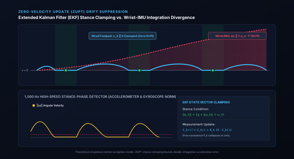
delta_p(t) ≈ 1/2 · eps_a · t^2 + 1/6 · (eps_g × g_n) · t^3A wrist is never at rest during the gait cycle. Wrist IMUs, such as those in the Garmin Fenix 8 or Apple Watch Ultra 2, therefore cannot separate translational acceleration from rotational arm-swing acceleration without statistical regression models.
Stance-Phase Zero-Velocity Updates (ZUPT)
A foot-mounted sensor can bound this divergence with Zero-Velocity Update (ZUPT) clamping. During mid-stance (roughly 80–140 ms of the contact phase), the shoe sole is stationary relative to the ground:
v_n(t) = 0, for all t in [t_flat_foot, t_heel_off]A stance-detection state machine flags this condition when the angular-rate norm falls below a threshold (|w_k| < w_th) and the acceleration norm is close to local gravity (| |a_k| - g | < a_th). It then injects a zero-velocity pseudo-measurement into an Extended Kalman Filter (EKF):
K_k = P_k⁻ · H^T · (H · P_k⁻ · H^T + R)^-1

x_k⁺ = x_k⁻ + K_k · (0 - H · x_k⁻)

P_k⁺ = (I - K_k · H) · P_k⁻
The residual (0 - H · x_k⁻) is a direct measurement of accumulated velocity drift, and the error covariance P_k shrinks at each update. Velocity error is therefore bounded to roughly one stride rather than growing without limit. This is why foot-based distance and pace estimates do not depend on GPS reception under tree cover or between buildings. Residual error still comes from stance-detection thresholds, heading drift and surface compliance.
2. McMahon & Cheng Spring-Mass Dynamics & Bilateral Asymmetry
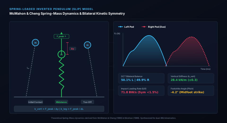
Running energetics are classically modeled with the Spring-Loaded Inverted Pendulum (SLIP) paradigm of Blickhan (1989), extended by McMahon & Cheng (1990). Rather than a rigid multibody chain, the leg behaves as a spring that stores and returns elastic energy at each footfall.
Mechanical Stiffness Derivations
Spring-mass analysis yields two standard stiffness parameters: vertical stiffness (k_vert) and leg spring stiffness (k_leg).
-
Vertical stiffness (k_vert): the ratio of peak vertical ground reaction force to the vertical displacement of the center of mass (COM):
k_vert = F_peak / delta_y_COMF_peak occurs near midstance (contact time t_c). delta_y_COM comes from double integration of vertical acceleration (a_z - g).
-
Leg spring stiffness (k_leg): accounts for initial leg length (L_0) and the leg’s compression over the contact phase (Morin et al., 2005):
k_leg = F_peak / delta_L

delta_L = L_0 - sqrt( L_0^2 - (v · t_c / 2)^2 ) + delta_y_COM
Leg stiffness that is too low implies excess energy dissipation through eccentric muscle work. Stiffness that is too high implies larger peak impact transmission to bone and cartilage.
Dual-Pod Bilateral Kinetic Symmetry
A single footpod or a wrist wearable cannot separate left-limb from right-limb loading. A two-pod system can, in principle, compare limbs directly:
- Ground Contact Time (GCT) Balance: compares the stance duration of each foot as a percentage split (for example 50.2% L / 49.8% R). Published gait literature associates larger asymmetries with fatigue, compensation or injury history, but there is no universal threshold.
- Impact Loading Rate (ILR): the time derivative of vertical force during the passive impact transient (dF_z/dt over roughly the first 20% of t_c). Between-limb differences point to unequal shock absorption.
- Footstrike Angle (FSA): the sagittal foot pitch at initial contact, commonly classed as rearfoot (below -5°), midfoot (-5° to 5°) or forefoot (above 5°).
3. Fluid Dynamic Drag Modeling: Pitot-Tube Pressure Sensing
Total mechanical running power is commonly decomposed as:
P_mech = P_kin + P_pot + P_int + P_aeroKinetic power (P_kin) and potential power (P_pot) cover forward and vertical COM motion, and P_int covers internal limb work. Aerodynamic power (P_aero) grows with the cube of speed:
P_aero = F_drag · v_runner = 1/2 · rho · C_d A · v_app^2 · v_runnerWhere:
- rho is air density (kg/m^3), dependent on barometric pressure and temperature.
- C_d A is the effective aerodynamic drag area, with the literature suggesting roughly 0.24–0.32 m^2 for an upright runner.
- v_app is the apparent wind velocity relative to the runner.
- v_runner is the runner’s ground velocity.
For a derivation of how apparent wind is obtained from a pressure port, see the pitot relation later in this section.

Figure 1: Stryd Pitot-static differential pressure dynamic airflow instrumentation and aerodynamic power derivation pipeline.
Why Weather APIs Are a Weak Wind Model
Wrist-based power estimates that correct for wind typically rely on hourly third-party weather data synced through a phone. Three physical factors limit that approach:
- Microclimate boundary layers: airport wind reported at a 10 m mast height can differ greatly from wind at 1–2 m, where buildings, fences and foliage create turbulence.
- Drafting: Pugh (1970) reported that running closely behind another runner cuts aerodynamic drag substantially and lowers oxygen cost at middle-distance speeds. A weather API cannot tell whether you are in clean air or behind a pack.
- Gust latency: gusts change over sub-second timescales, while API data are static averages.
The Pitot Dynamic Pressure Principle
A pitot-style differential pressure port measures stagnation pressure (P_stag) against static ambient pressure (P_stat). From Bernoulli’s principle:
delta_P = P_stag - P_stat = 1/2 · rho · v_app^2

v_app = sqrt( 2 · delta_P / rho )
Stryd describes a pressure port in the pod for this purpose. Measuring dynamic pressure at the shoe can capture headwinds, tailwinds and drafting effects in near real time, though foot-level airflow is disturbed by the runner’s own leg motion and body wake, so the reading is an estimate of wind, not a clean freestream measurement.
4. Stryd Duo vs. Wrist-Based Running Power Engines
To understand the engineering distinctions between foot-level kinetics and wrist-level heuristics, consider the architectural comparison below:
| Technical Dimension | Stryd Duo Dual Pods | Garmin Running Dynamics (Fenix 8) | Apple Watch watchOS (Ultra 2) |
|---|---|---|---|
| Sensor Placement | Bilateral Tarsal (Shoe Laces) | Distal Radius / Ulna (Wrist) | Distal Radius / Ulna (Wrist) |
| IMU Sampling Rate | 1,000 Hz internal / 100 Hz out | 50–100 Hz | 50–100 Hz |
| Drift Mitigation | ZUPT (Velocity reset each stance) | Statistical Kalman + GPS fusion | Statistical Machine Learning Model |
| Ground Contact Estimation | Direct stance-phase IMU clamping | Derived from arm-swing deceleration | Derived from torso-harmonic estimation |
| Wind Resistance | Differential Pitot Tube (delta_P) | Cellular Weather API + Altimeter | Cellular Weather API + Barometer |
| Incline Responsiveness | Instant pitch rate integration | Barometric lag (2–4 s filter delay) | Barometric lag (2–4 s filter delay) |
| Bilateral Asymmetry | Full (GCT, ILR, FSA, Balance) | None (single wrist) | None (single wrist) |
| Weight Penalty | 8g per pod (16 g total) | 0 g (integrated in watch) | 0 g (integrated in watch) |
Wrist-based algorithms function adequately under steady-state conditions on flat asphalt. However, when cadence decouples from speed (e.g., steep grade ascents, technical trail terrain, or bounding drills), wrist heuristics break down because arm swing no longer tracks lower-extremity kinetics.
5. Critical Power Modeling & Practical Prescription
The practical application of Stryd Duo power output is grounded in the Critical Power (CP) concept (Monod & Scherrer, 1965), which models the hyperbolic boundary between sustainable oxidative metabolism and non-sustainable metabolic fatigue:
P(t) = CP + W' / tWhere:
- CP is the asymptote representing Critical Power (analogous to the physiological maximal metabolic steady state or MLSS).
- W’ is the finite anaerobic work capacity (expressed in Joules or kilojoules), available for work performed strictly above CP.
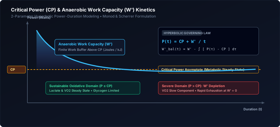
Figure 2: Hyperbolic Critical Power (CP) duration boundary and finite Anaerobic Work Capacity (W’) depletion kinetics.
Because a power metric accounts for gradient and wind drag, runners can pace across hilly terrain and shifting headwinds at a constant metabolic strain rate, rather than chasing variable pace metrics that can cause premature W’ depletion.
6. Engineering Verdict & Technical Assessment
This verdict rests on sensor architecture and published methods, not on our own measurements.
- Kinematic approach: foot-mounted IMUs with ZUPT stance clamping bound integration drift to one stride, which is architecturally stronger than inferring foot motion from the wrist.
- Fluid dynamics: a pitot-style pressure port is a physically sound way to estimate apparent wind and drafting, subject to the foot-level airflow caveats above.
- Bilateral insight: two synchronized pods expose contact-time, impact-rate and strike differences that single-sensor wearables cannot see.
- Form factor and friction: pods must be attached to the shoes and charged. At about 8 g each they are light, but they require more upkeep than an all-in-one watch.
For runners who want biomechanically grounded kinetic modeling rather than statistical wrist regressions, the Stryd Duo is the most architecturally rigorous consumer option we have analyzed.
Deploy Stryd Duo Biomechanical Precision
Equip dual-footpod 1,000 Hz IMU kinematics, direct ZUPT drift suppression, and wind-compensated power modeling for your training pipeline.
References
- Blickhan, R. (1989). The spring-mass model for running and hopping. Journal of Biomechanics, 22(11-12), 1217-1227.
- McMahon, T. A., & Cheng, G. C. (1990). The mechanics of running: how changes in leg stiffness affect ground reaction forces. Journal of Biomechanics, 23, 65-78.
- Pugh, L. G. (1970). Oxygen intake in track and treadmill running with observations on the effect of air resistance. The Journal of Physiology, 207(3), 823-835.
- Cavagna, G. A., Heglund, N. C., & Taylor, C. R. (1977). Mechanical work in terrestrial locomotion: two basic mechanisms for minimizing energy expenditure. American Journal of Physiology, 233(5), R243-R261.
- Morin, J. B., Dalleau, G., Kyröläinen, H., Jeannin, T., & Belli, A. (2005). A simple method for measuring stiffness during running. Journal of Applied Biomechanics, 21(2), 167-180.